How to Choose the Right Linear Motor for Your Application?
Choosing the right linear motor begins with understanding the application, not browsing product catalogs. A factory engineer may need fast positioning, while a laboratory stage may prioritize nanometer-level repeatability. These requirements can look similar on paper, yet they produce very different motor choices.
A reliable selection process examines continuous force, peak force, stroke length, speed, acceleration, and duty cycle. It also considers payload, friction, mounting stiffness, encoder resolution, and thermal conditions. For example, a motor moving a 12-kilogram carriage at high acceleration may require more peak force than its average load suggests. Cable routing and contamination deserve attention too. Small design details often become expensive problems later.
Real-world testing matters. Datasheets provide valuable limits, but they cannot predict every vibration pattern, bearing issue, or control response. A calculation may appear correct and still fail in production. That is worth remembering. Engineers should compare manufacturer specifications, verify operating assumptions, and test the linear motor under representative loads. Independent standards, documented measurements, and supplier support can strengthen the decision. The best choice balances performance, reliability, energy use, integration effort, and long-term maintenance. It should not simply deliver the highest speed. It should deliver repeatable results when the machine is warm, busy, and slightly less perfect than the original design.
Define the Motion Requirements of Your Application
How to Choose the Right Linear Motor for Your Application?
Define the Motion Requirements of Your Application
Start with the motion profile, not the motor catalogue. Record stroke length, payload, travel speed, acceleration, repeatability, and operating cycle. A 500 mm stroke at 2 m/s demands a different solution from a 50 mm inspection movement. Include settling time. It often controls productivity more than peak speed.
Calculate continuous and peak force separately. Moving force includes acceleration, friction, gravity, cable drag, and process resistance. The U.S. Department of Energy reports that motor-driven systems consume more than half of industrial electricity. Efficient sizing therefore affects both performance and operating cost. Oversizing wastes energy and may reduce responsiveness.
Check the full duty cycle. A motor reaching 1,000 N briefly may overheat under repeated acceleration. According to the International Federation of Robotics’ World Robotics 2024 report, approximately 541,000 industrial robots were installed globally in 2023. That scale increases demand for predictable, high-cycle motion. Still, published figures do not replace testing. A spreadsheet can lie.
Define the environment carefully. Dust, cleanroom rules, heat, vibration, and vertical loads change the design. Specify encoder resolution, allowable positioning error, and controller compatibility. Leave realistic margins, but avoid arbitrary safety factors. Measure the real load if possible. Your first estimate may be wrong. That is useful information, not failure.
Compare Linear Motor Types and Operating Principles
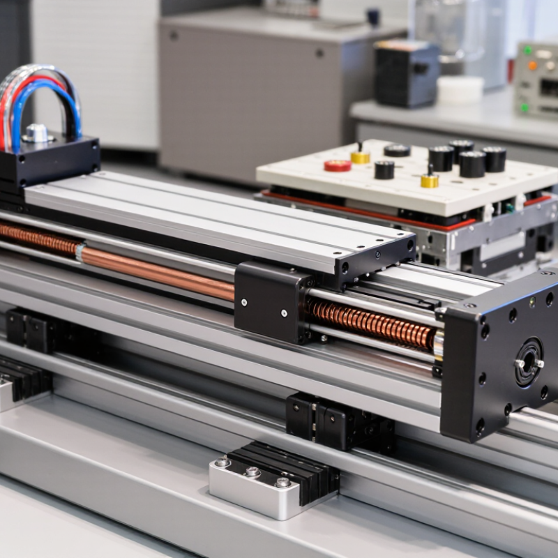
Choosing a linear motor starts with its operating principle, not its catalog speed. A permanent-magnet field interacts with controlled electromagnetic currents. This creates direct linear force without screws, belts, or gearboxes. Iron-core motors provide high force density and tolerate demanding acceleration. However, their magnetic attraction can increase cogging and force ripple. Ironless motors reduce ripple and moving mass. They suit scanning, inspection, and semiconductor positioning. Tubular motors offer compact cylindrical layouts. Voice-coil actuators deliver short strokes and precise force control, but they usually lack continuous travel.
Application data should guide the comparison. Calculate force from payload, acceleration, friction, and safety margin. Then check continuous force, peak force, stroke, duty cycle, cooling, and feedback resolution.
According to the International Federation of Robotics World Robotics 2024 report, 541,302 industrial robots were installed globally in 2023. This growth increases demand for faster, cleaner, and more repeatable motion systems. The U.S. Department of Energy reports that motor-driven systems can represent more than 70% of industrial electricity consumption. Therefore, efficiency deserves equal attention.
In practical testing, thermal behavior often surprises engineers. Peak acceleration may look excellent for ten seconds. Continuous performance can be very different. I would compare measured temperature, settling time, and noise under the real load.
Not just brochure values.
A heavier iron-core design may win in pressing applications. An ironless design may perform better in fragile optical inspection. The best choice depends on the entire motion profile, including pauses, reversals, contamination, and maintenance access. A perfect selection rarely exists. Even reliable calculations need physical validation.
Match Motor Performance to Load, Speed, and Accuracy
How to Choose the Right Linear Motor for Your Application?
Match Motor Performance to Load, Speed, and Accuracy
Choosing a linear motor starts with the real load, not the catalog rating. Measure the moving mass, friction, cable drag, and vertical force. Measure the real load. A motor must provide enough continuous force for normal motion and enough peak force for acceleration. If the load changes often, calculate several operating cases instead of using one average value.
Speed and accuracy must be evaluated together. High speed may increase vibration, settling time, and heat. Define the required travel distance, acceleration, positioning tolerance, and cycle time. For a dispensing axis, a small positioning error can affect material volume. For inspection equipment, repeatability may matter more than maximum speed. Feedback resolution, mechanical stiffness, and controller tuning also influence the final result.
Thermal performance deserves close attention.
Continuous current can heat the motor, especially inside a narrow enclosure. Check the duty cycle, ambient temperature, cooling method, and allowable winding temperature. A smaller motor may fit physically but fail during repeated cycles. I have seen early selections based on peak force alone, followed by disappointing thermal results. That mistake is easy to make. Review force-speed curves, confirm the safety margin, and test the complete axis under realistic conditions. The best choice is not always the fastest motor. It is the motor that maintains load capacity, speed, and accuracy throughout actual operation.
Evaluate Control, Feedback, and Integration Requirements
When choosing a linear motor, treat control and feedback as one engineering decision. A fast motor is useless if the controller cannot close the loop reliably. Define stroke, force, settling time, and duty cycle before comparing catalog values. Then map each requirement to the drive’s command interface, update rate, and tuning tools. A 1-micron encoder does not guarantee 1-micron positioning. Cable flex, thermal growth, vibration, and servo-loop delay still matter.
Deloitte’s 2024 Smart Manufacturing and Operations Survey reported that 92% of manufacturers viewed smart manufacturing as a primary competitiveness driver. The International Federation of Robotics’ World Robotics 2024 report recorded 541,302 industrial robot installations in 2023. These figures indicate growing pressure for predictable, connected motion systems. Select controllers that support deterministic communication, clear diagnostics, and accessible parameter data. Confirm compatibility with the PLC, safety circuit, human-machine interface, and factory network before purchasing.
Feedback selection deserves practical testing.
Compare linear encoders, Hall sensors, and motor-current feedback under real temperature and vibration conditions. Check sampling frequency, latency, resolution, and signal noise. During commissioning, record following error at low speed and during sudden reversals. A common mistake is trusting laboratory accuracy. The machine may behave differently. I would also challenge the first design: extra resolution can increase cost and tuning difficulty without improving production quality. Build a small integration test, expose the weak points, and revise the specification before final selection.