10 Tips for Choosing the Best Temperature Sensor?

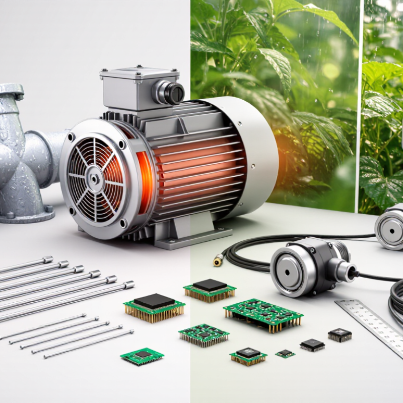
Choosing the best temperature sensor is not just a matter of picking the most accurate model. The right choice depends on what you need to measure, where the sensor will operate, and how its readings will guide decisions. A probe mounted in a chilled pipe faces different demands from one installed beside a hot motor or inside a humid greenhouse. Range, response time, accuracy, durability, and compatibility all matter. Small details matter.

This guide outlines ten practical points to consider before selecting a temperature sensor. It covers common sensor types, operating conditions, installation, wiring, calibration, and the requirements of your monitoring system. A datasheet can help, but its figures need context: accuracy may vary across the stated range, and response time can change with the probe’s size and mounting. Check how the sensor will be attached, whether its materials suit the environment, and how often readings must be taken. There is no universally best choice, which can be frustrating. Even a well-specified sensor may give poor results if it is installed carelessly or checked too rarely. Consider the whole measurement setup, not just the sensor itself. These tips can help narrow the options, though unusual applications may still require advice from a qualified instrumentation professional.

10 Tips for Choosing the Best Temperature Sensor?

Define the Temperature Range and Measurement Requirements

Before comparing temperature sensors, record the lowest and highest temperatures the process may reach—not just its normal operating point. Include start-up, cleaning cycles, faults, and nearby heat sources. A freezer line may sit at -18°C but warm during defrost. A sensor near a hot pipe may read differently from one in the process itself. Leave room beyond the expected extremes; operating at a sensor’s limit can affect accuracy or service life.

Define what “good measurement” means for your application. Is an accuracy of ±0.5°C enough, or must the sensor detect smaller changes? Check accuracy across the full temperature range, and specify response time, repeatability, and acceptable drift. A fast probe can track a moving fluid, while a heavier probe may smooth brief spikes. That may hide useful information. Also note whether the sensor measures air, liquid, or a surface, since placement affects readings.

Tips: Make a requirement sheet listing temperature range, target accuracy, response time, medium, and installation depth. Check that the controller accepts the sensor’s output. This detail is easy to miss. Test it cold. If the setup allows, trial a sample sensor in real operating conditions before finalizing the specification; a tidy range on paper may not reflect how heat moves around the installed sensor.

10 Tips for Choosing the Best Temperature Sensor

Tip 1: Define the temperature range and measurement requirements.

Representative ranges vary with sensor design, probe materials, and measurement equipment. Choose a sensor rated for the full expected temperature range, then check its accuracy, response time, and environmental suitability.

Compare Common Temperature Sensor Types

Temperature sensors differ in range, accuracy, response time, and installation needs. A thermocouple handles very high temperatures and responds quickly, which suits ovens, furnaces, and moving equipment. Its readings can drift, though, so calibration and careful wiring matter. It may be excessive for a room-temperature monitor.

An RTD, often made with a platinum element, offers stable, repeatable readings across many industrial processes. It usually costs more and may respond slower than a thermocouple.

Thermistors are compact and sensitive over a narrower range, making them useful in appliances, battery packs, and medical equipment. Their steep response can be helpful, but it also makes the useful range less forgiving. Small placement errors matter.

Semiconductor sensors are convenient for circuit boards and indoor devices, especially when digital output is useful. They generally suit moderate temperatures, not intense heat. Infrared sensors measure surface temperature without touching the target; aim them at a moving part or hot pipe, but remember that distance, shiny surfaces, and dust can distort readings.

There is no universal winner. This comparison is imperfect: sensor accuracy on paper cannot fix poor mounting. A probe pressed against a cold metal bracket may report the bracket, not the fluid inside the pipe. Check the temperature range, response time, environment, and maintenance plan before choosing.

Assess Accuracy, Response Time, and Stability

Accuracy begins with the process, not the catalog. Define the operating range, allowed error, and calibration conditions before comparing sensors. IEC 60751:2022 specifies Class A platinum resistance thermometer tolerance as ±(0.15 + 0.002|t|)°C. At 100°C, that equals ±0.35°C; Class B allows ±0.8°C. These figures describe tolerance, not guaranteed performance in your installation. Check the probe, readout, wiring, and calibration uncertainty as one measurement chain.

Response time matters when temperatures change quickly. Ask for the time constant, commonly measured as the time to reach 63.2% of a step change, and check the test medium and mounting conditions. A probe tested in moving water may respond differently when pressed against a metal pipe. Test it installed. A fast reading can still be wrong if the sensor sits in a stagnant pocket or misses the hottest spot.

Stability is the quiet cost. Review drift data across the intended temperature range, then set a calibration interval that reflects use, vibration, and thermal cycling. ASTM E230/E230M lists Type K thermocouple tolerances, including ±1.1°C or ±0.4% for special limits, whichever is greater. A tight initial tolerance does not promise low drift over time. Keep calibration records and compare repeat readings under the same conditions. One practical flaw: real processes rarely hold perfectly steady, so field checks may reveal more than a tidy laboratory number.

Evaluate Environmental Conditions and Sensor Materials

Start with the installation, not the catalog. Record the temperature range, ramp rate, humidity, vibration, pressure, and chemicals near the sensing tip. Check whether washdowns, condensation, or thermal cycling reach the sheath, cable, or junction. Small details matter. NIST Monograph 175 lists Type K thermocouple reference tables from approximately −270°C to 1372°C. That range describes reference data, not guaranteed accuracy or service life. IEC 60584-1 also provides reference tables for thermocouple types; compare the selected type’s limits with actual operating conditions.

Then assess material compatibility. A sheath exposed to process chemicals may corrode even when temperatures seem acceptable. Stainless steel can suit some environments, while aggressive media may require another compatible alloy or a ceramic protection tube. Verify the chemistry and exposure time; “corrosion-resistant” is not universal. Platinum resistance sensors offer stable, predictable readings in suitable ranges, but their assemblies still need protection from contamination and mechanical shock. Thermocouples can cover broad ranges, depending on type and construction. The awkward part is that sensor material, sheath, and seal may fail differently. Check each component, and leave room for recalibration when drift matters.

Plan Installation, Calibration, and Maintenance

Tip 1 — Plan installation around the process, not the easiest mounting point. Place the probe where temperature changes are representative, away from heaters, open doors, and stagnant corners. In a pipe, check insertion depth and use a suitable thermowell when pressure or cleaning requirements demand one. Route cables away from motors and other electrical noise sources. Leave room to remove the sensor later. A quick installation sketch can reveal awkward access before work begins.

Tip 2 — Set a calibration plan before relying on readings. Compare the sensor with a suitable reference instrument across the temperatures that matter to your process. Record the results, reference instrument, date, and any adjustment. Use an interval based on operating conditions, risk, and observed drift; there is no universal schedule. If readings affect product quality or equipment protection, define acceptable limits and what staff should do when results fall outside them.

Tip 3 — Treat maintenance as a routine, not a repair response. Check connections, seals, probe surfaces, and cable wear during planned inspections. Look for corrosion, residue, loose fittings, or sudden changes from the normal reading. Keep a simple log so gradual drift is easier to spot. One detail is easy to overlook: cleaning methods can damage some probes. Confirm the sensor’s limits before cleaning, and revise the schedule when inspections show it is not working well.

10 Tips for Choosing the Best Temperature Sensor: Plan Installation, Calibration, and Maintenance

Tip What to Evaluate Practical Guidance Installation, Calibration, or Maintenance Check
1. Define the operating range Minimum, normal, and maximum process temperatures, including start-up or fault conditions. Choose a sensor and protective assembly rated for the full expected range. The usable range depends on the sensor construction, sheath, insulation, and measurement electronics. Confirm that the entire measurement chain—not just the sensing element—is rated for the process conditions.
2. Set accuracy and stability requirements Required measurement uncertainty, repeatability, and acceptable drift over time. RTDs often provide stable, accurate measurements over moderate ranges; thermocouples suit broad temperature ranges; thermistors can offer high sensitivity over a more limited range. Compare complete specifications rather than sensor type alone. Include instrument, wiring, installation, and calibration contributions when estimating total measurement uncertainty.
3. Match the sensor to the process Temperature range, response needs, vibration, pressure, and chemical exposure. Consider RTDs, thermocouples, thermistors, or infrared sensors according to the application. Select a sheath, probe, or protective well compatible with the process material and conditions. Check material compatibility and mechanical ratings against the process fluid, pressure, vibration, and cleaning method.
4. Plan the measurement location Whether the chosen point represents the temperature of interest. Place contact sensors where they can measure the process rather than a nearby wall, stagnant region, or heat source. Avoid locations affected by unexpected mixing or temperature gradients. Document the sensor location and insertion depth so the reading can be interpreted and reproduced.
5. Allow suitable immersion Heat transfer along the probe and from the process to the sensing element. Provide enough insertion to reduce heat loss or gain through the stem. A thermowell can improve protection and allow removal, but it may slow response. Review the installation design for adequate immersion, secure mounting, and acceptable response time.
6. Check response time How quickly the process temperature can change and how quickly the measurement must follow. Small sensing elements generally respond faster than larger assemblies. Protective covers, thermowells, and heavy probe construction can add thermal lag. Compare response requirements with the installed assembly, not only the bare sensing element.
7. Confirm wiring and signal compatibility Input type, cable length, electrical noise, and transmitter or controller requirements. RTDs may use 2-, 3-, or 4-wire circuits; additional wires can help compensate for lead resistance. Thermocouple installations require compatible extension wire and cold-junction compensation. Verify sensor type, polarity where applicable, wiring method, input configuration, and grounding against the instrument documentation.
8. Use infrared sensors only when appropriate Surface emissivity, field of view, target size, and obstructions. Infrared sensors measure emitted radiation from a surface without contact. Reflections, transparent barriers, changing emissivity, dust, or steam can affect readings. Ensure the target fills the sensor’s field of view and configure emissivity appropriately for the surface.
9. Establish a calibration plan Measurement criticality, operating conditions, drift history, and applicable quality requirements. Use calibration equipment and procedures appropriate to the sensor’s range and required uncertainty. Set intervals according to risk and observed performance rather than assuming one interval fits every application. Record as-found and as-left results, reference equipment, conditions, and any adjustments or out-of-tolerance findings.
10. Plan inspection and replacement Corrosion, contamination, mechanical damage, loose connections, and changing process conditions. Routine checks can identify damaged sheaths, deteriorated cables, poor connections, or unusual measurement drift before they affect process control. Define inspection and replacement criteria, keep installation records, and reassess the sensor when the process or operating environment changes.