Minimal Space. Maximum Impact! Designed for when every millimeter matters> the new IRONLESS UNANO SERIES
Semiconductors
Increase throughput and precision of your system
Display
Enhance accuracy and precision with linear motors
Science and aerospace
Improve motion quality for a variety of applications
Machine tooling
Robust solutions for increased speed and precision
Digital cutting
Create modular and high throughput applications
Printing
Increase printing speed and quality using linear motors
Robotics
Integrate compact solutions for guaranteed uptime and high dynamics
Life science
Establish precise and clean integrated solutions
Woodworking
Maximize performance and accuracy for high throughput
Stages and system solutions
Compact integration and high performance for your axis
Vacuum applications
Best performance for clean and vacuum applications
Characteristics
Choosing a torque motor begins with the job it must perform, not a catalogue headline. A motor that delivers impressive peak torque may still struggle during a long, slow cycle. Start by documenting the load, required speed, acceleration, operating hours, and available space. Include the actual working pattern, such as frequent starts or extended holding. Small details matter.
Next, compare continuous and peak torque ratings with the demands of your application. Check load inertia, thermal limits, cooling, and the drive’s current capacity. In a direct-drive system, the motor may connect straight to the mechanism, reducing the need for gears. That can simplify the assembly, but it does not remove the need to check stiffness, bearing loads, and positioning accuracy. Keep the numbers close. A spreadsheet helps.
The installation environment also shapes the choice. Dust, heat, vibration, and limited airflow can affect performance over time. Ask suppliers for complete torque-speed curves, temperature limits, and compatible drive specifications. Confirm that test conditions match your real duty cycle; ratings can be misleading without context. This guide explains how to weigh these factors, compare motor designs, and avoid common sizing mistakes. No selection method is perfect. Recheck assumptions against measured loads, especially when the machine behaves differently from its original design estimate.
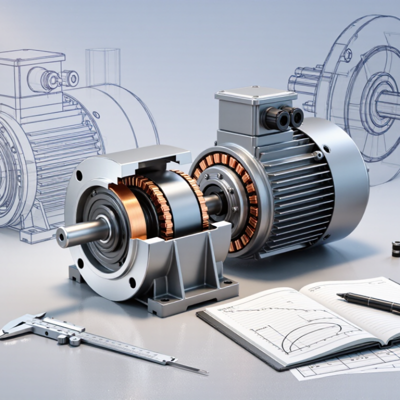
A torque motor is designed to produce useful torque at low or zero speed, often without a gearbox. Its rotor turns the load directly, while current in the stator windings creates a magnetic field that drives rotation. The controller adjusts current and commutation to set torque and speed. Unlike a high-speed motor with reduction gearing, this arrangement can reduce backlash and simplify the mechanical train. That matters.
Selection begins with the load, not a catalog headline. Estimate required continuous torque, peak torque, speed, acceleration, and duty cycle under real operating conditions. A positioning table moving a heavy fixture may need brief high torque during acceleration, but less torque while holding. Check rotor inertia and feedback needs, too; a motor can meet its torque rating and still feel sluggish. Heat adds up. Continuous current warms the windings, so cooling and ambient temperature affect usable output.
Tips: Compare continuous and peak torque separately, then check speed-torque curves and thermal limits in the technical data. Leave margin for friction, load changes, and imperfect measurements. A little uncertainty is normal; test the actual assembly before finalizing the motor.
| Selection Dimension | What It Means | Practical Selection Guidance | Example or Check |
|---|---|---|---|
| Operating principle | A direct-drive torque motor produces rotary motion without a gearbox. In a typical permanent-magnet synchronous design, the rotor’s magnets interact with the stator’s controlled magnetic field to generate torque. | Consider direct drive when eliminating gear backlash, transmission wear, or maintenance is important. The motor must provide the required torque directly at the load. | Applications include rotary tables, indexing axes, robotic joints, and winding equipment. |
| Continuous torque | The torque the motor can deliver continuously without exceeding its specified thermal limits under stated cooling and ambient conditions. | Calculate the RMS torque over the complete operating cycle, including acceleration, steady operation, and deceleration. Select a motor whose continuous rating meets or exceeds this value with suitable margin. | For a repeating cycle, use the torque and duration of each segment to calculate RMS torque; do not size from peak torque alone. |
| Peak torque | The short-duration torque available for acceleration, deceleration, or brief load changes. The allowable duration depends on the motor and drive limits. | Check the motor’s peak-torque time limit and the drive’s current limit. Confirm that the required peak torque can be produced without exceeding either limit. | For an inertia-dominated axis, estimate acceleration torque using T = J × α, then add the torque required by the external load. |
| Speed and torque curve | Available torque can decrease as rotational speed rises because of voltage, back-EMF, current, and thermal constraints. | Check the torque available at the actual operating speed, not only the motor’s maximum or stall torque. Confirm that the drive bus voltage supports the required speed. | Review the manufacturer’s continuous and peak torque-speed curves at the intended supply voltage and cooling condition. |
| Load inertia and acceleration | The motor must accelerate the combined inertia of the rotor, tooling, workpiece, and any other rotating parts. | Estimate total inertia about the motor axis and calculate the acceleration and deceleration demand. Include friction and process torque in the load estimate. | For a rotating body, acceleration torque is approximately the total rotational inertia multiplied by angular acceleration. |
| Positioning accuracy and feedback | Torque motors are commonly paired with an encoder or resolver so a servo drive can control position, speed, and torque. | Choose feedback resolution and accuracy based on the system’s positioning requirement. Account for encoder mounting, alignment, and control-system performance. | Fine positioning may require a high-resolution feedback device and a rigid, low-compliance mechanical structure. |
| Thermal management | Motor losses generate heat, and winding temperature limits affect continuous torque capability and service life. | Verify the rated ambient temperature, mounting conditions, cooling method, and duty cycle. Forced-air or liquid cooling may be needed for high continuous torque in a compact space. | Compare ratings only when their specified cooling method and thermal conditions are understood. |
| Mounting and rotor configuration | Frameless torque motors are installed directly into a machine structure; housed versions include a supporting enclosure and bearings. | For frameless designs, check the machine’s bearing arrangement, air gap, alignment, stiffness, and assembly process. For housed designs, verify mounting dimensions and shaft or rotor interface. | Frameless motors can save space but require careful mechanical integration and alignment. |
| Drive and electrical compatibility | The servo drive must match the motor’s voltage, current, feedback, and commutation requirements. | Confirm continuous and peak phase-current requirements, DC bus voltage, feedback type, and compatible control modes before selecting the motor-drive combination. | Check both the motor’s electrical specifications and the drive’s output ratings at the intended operating conditions. |
| Application environment | Dust, moisture, chemicals, vibration, and temperature can affect motor performance and required protection. | Specify the environment and required enclosure or protective measures. Frameless motors may need machine-level sealing because they do not provide a complete enclosure by themselves. | For washdown or dusty areas, verify the protection level of the complete installed assembly, not just the motor component. |
| Final sizing check | A suitable motor must satisfy torque, speed, thermal, mechanical, and control requirements together. | Validate the proposed motor using the full motion profile and actual load data. Confirm continuous torque, peak duration, maximum speed, inertia, cooling, and drive compatibility. | Use application-specific calculations and the motor manufacturer’s published curves before finalizing the selection. |
Start with the load, not the motor catalog. Record the mass, radius, friction, and any force acting against rotation. For a turntable, for example, note the payload’s distance from the shaft; that distance affects the inertia the motor must accelerate. Estimate both continuous torque and short peak torque. Peak demand may occur during startup, rapid direction changes, or a sudden increase in load. Close estimates matter.
Then describe the motion in practical terms. What speed is needed? How quickly must the motor reach it, stop, or reverse? Include the operating cycle, such as repeated 90-degree indexing with pauses. These details help reveal whether the motor can manage acceleration and heat over time, rather than just meet a brief torque target. Don’t overlook gravity. A vertical axis may need continuous holding torque, even when it appears stationary.
Set measurable performance limits: positioning accuracy, speed variation, noise, and available space. Check the motor’s thermal limits against the real duty cycle, and allow for friction or load changes that are hard to predict. A spreadsheet helps, but it can create false confidence. Test the motion with the actual mechanism when possible. Real hardware can surprise you.
Start with the load, not the motor catalog. Record the required shaft torque throughout the motion: acceleration, steady travel, and braking. A rotary table carrying a 12-kilogram fixture may need a brief torque peak to start, then much less torque while indexing. Include friction, gravity, and transmission losses. Check the torque-speed curve at the actual operating voltage; available torque can drop as speed rises. Also confirm that the motor can reach the required speed without exceeding its mechanical limit.
Tips: Measure the load if possible. Estimate inertia and cycle time, then calculate RMS torque across the full duty cycle. Compare it with the motor’s continuous rating, not just its peak rating. Measure it warm. A first estimate is only a model; friction and settling time can surprise you.
Duty cycle affects heat, even when peak torque looks acceptable. For repeated starts, stops, or long holding periods, check winding temperature limits and cooling conditions. A motor holding a vertical load may draw substantial current while stationary. Leave sensible margin for changing payloads and real-world variation, but avoid oversizing without a reason; a larger motor can increase cost and inertia. Revisit the assumptions after testing the assembly under its expected load.
Thermal limits often decide whether a torque motor can deliver its rated performance in real use. Compare continuous torque with the actual duty cycle, not just peak torque on a specification sheet. A motor holding a load for several minutes may heat differently from one moving intermittently. Check winding temperature, cooling method, and ambient conditions. A motor mounted inside a warm enclosure may need more thermal margin.
Mechanical fit matters just as much. Confirm shaft dimensions, allowable radial and axial loads, and rotor inertia. A direct-drive setup can remove gears, but it also places the load directly on the motor. Measure the load’s inertia and consider how quickly it must accelerate or stop. Vibration can appear at certain speeds. Small details count.
Control requirements shape the final choice. Match the motor’s feedback device and commutation method to the drive, then check that the drive can supply the required current. Verify speed range, positioning accuracy, and response to changing loads. A control loop tuned for a light test fixture may behave poorly on a heavier machine. Early calculations are useful, but they are still estimates; testing the motor with the real load can reveal heat or vibration that a datasheet cannot.
Illustrative calculation for a load that applies 20 Nm of torque during each 2-second cycle and zero torque otherwise. RMS torque is calculated as peak torque × √(duty cycle); with a constant torque constant and winding resistance, copper loss is proportional to RMS torque squared. Use the actual load profile to check continuous and peak torque, then verify operating speed, inertia, thermal limits, and control bandwidth against the motor and drive specifications.
Comparing motor options begins with the motion, not the catalog rating. A direct-drive torque motor can provide smooth, precise rotation without gearbox backlash. It suits indexing tables, rotary joints, and other loads that benefit from low-speed control. A geared servo may offer more output torque in a compact package, but gearing adds friction, wear, and possible lost motion. Stepper motors can be practical for simple positioning, though demanding loads may cause missed steps.
Check the full torque-speed curve rather than relying on peak torque alone. Peak torque is usually available only briefly; continuous torque must match the real duty cycle. Include acceleration, load inertia, friction, and any force from an offset payload. Small details matter. A heavy fixture can change the sizing result more than expected.
Before final selection, compare required torque and speed against the motor’s continuous and peak limits, then review thermal data and feedback needs. Confirm that the drive can supply the required current and that the mounting space allows heat to escape. Real loads are messy. Test a representative assembly through repeated starts, stops, and operating cycles. Measure motor temperature and positioning error under load. One imperfect assumption can still slip through a calculation, so leave a sensible margin and revisit it after testing.