10 Tips for Choosing a Direct Drive Torque Motor?
Choosing a direct drive torque motor is not simply a matter of comparing catalog torque. The right decision connects load size, speed, accuracy, heat, feedback, and machine structure. A motor that looks powerful on paper may still struggle with friction, unbalanced tooling, or repeated acceleration.
This guide presents ten practical tips for evaluating motor options with greater confidence. It considers continuous and peak torque, rotor inertia, bearing capacity, cooling methods, encoder resolution, and operating environment. It also examines mounting space, cable routing, control compatibility, and supplier documentation. Small details matter. A few millimeters of misalignment can create vibration, noise, or premature bearing wear.
No checklist is perfect. Real machines behave differently from laboratory calculations. Engineers should verify estimates through load testing, thermal monitoring, and controlled commissioning. A supplier’s published curve is useful, but it should not replace application-specific validation. Questions about duty cycles, tolerances, service support, and replacement availability deserve direct answers. Some buyers also overlook the controller, assuming motor performance exists independently. It does not.
The following tips are designed for engineers, designers, and purchasing teams comparing direct-drive solutions. They encourage careful questioning rather than fast selection. When specifications conflict, document the trade-offs. When data is missing, treat that gap as a risk. A reliable motor choice supports stable positioning, predictable maintenance, and consistent production over time. That is the practical standard—not merely a higher torque number.
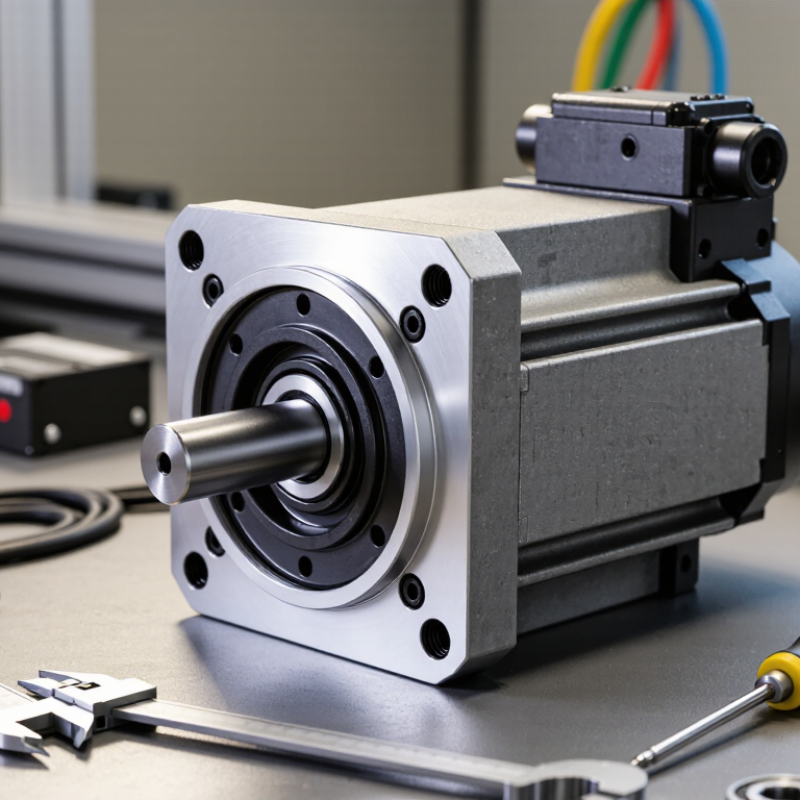
Define Torque and Speed Needs Across Typical 10–1,000 N·m and 10–1,000 rpm Ranges
10 Tips for Choosing a Direct Drive Torque Motor?
Define Torque and Speed Needs Across Typical 10–1,000 N·m and 10–1,000 rpm Ranges
Start with the real motion profile, not the motor catalogue. Record continuous torque, peak torque, operating speed, acceleration, and duty cycle. A machine needing 10 N·m at 1,000 rpm differs greatly from one requiring 1,000 N·m at 10 rpm. Calculate power with P = T × ω, then check whether torque and speed occur simultaneously.
Include friction, gravity, cutting forces, and reflected inertia. Peak torque may appear during acceleration, indexing, or sudden load changes. Continuous torque controls heating over time. Leave practical margin, but avoid excessive oversizing. A larger motor can increase cost, inertia, and control difficulty. That trade-off is often underestimated.
Check the load connection carefully. Direct drive removes gearbox backlash, yet shaft alignment becomes more important. Review bearing loads, radial forces, axial forces, and allowable overhung moments. Select feedback resolution according to positioning accuracy and speed stability. Confirm the drive can handle low-speed torque without ripple or overheating. Cooling may be necessary near 1,000 N·m, especially in compact housings. I have seen calculations fail because a short peak was treated as continuous duty. That mistake is easy to repeat. Recheck the profile with measured data, ambient temperature, emergency stops, and cable movement before approving the motor.
Compare Continuous and Peak Torque Ratings Against 40–100°C Thermal Limits
Choosing a direct drive torque motor starts with thermal evidence, not advertised peak force. Compare continuous torque at the actual housing temperature, especially across the 40–100°C range. IEC 60034-1 links motor ratings to defined thermal conditions, but real machines face restricted airflow, nearby heat sources, and changing duty cycles. A motor producing 120 Nm for two seconds may still overheat if repeated every five seconds. Peak torque is useful only when the drive, bearings, and winding insulation can tolerate the event.
Tip: Request a torque-speed-temperature map. Check continuous torque at 40°C, 60°C, 80°C, and 100°C. Then match each point with your cabinet temperature and cooling method. The U.S. Department of Energy’s Motor Systems Market Assessment reports that motor-driven equipment represents about 68% of industrial electricity use in the United States. Small efficiency losses can therefore become substantial operating costs. A thermal sensor near the winding is more convincing than a brochure graph.
Tip: Separate marketing peak torque from usable peak torque. Ask whether the rating assumes cold starts, forced cooling, or a short duty cycle. Industry testing under IEC 60034-1 can improve comparability, yet test conditions may not mirror a dusty production cell. I have seen designs pass a laboratory test and struggle beside a 90°C machine frame. Leave thermal margin. My own rule is conservative: if continuous torque is only slightly above the application requirement, reconsider the motor size. It costs more upfront, but thermal surprises cost more.
Evaluate Accuracy, Repeatability, Stiffness, and Runout Below 10 μm
Choosing a direct drive torque motor starts with the motion target, not peak torque. For precision rotary work, demand accuracy, repeatability, stiffness, and runout below 10 μm. ISO 230-2:2014 separates positioning accuracy from repeatability, so test both directions under realistic loads. A motor may repeat within 2 μm while its absolute position error exceeds 10 μm.
Measure the complete assembly. Include the bearing, encoder, coupling interface, fixture, and thermal condition. The ISO 230-2 method recommends recording bidirectional positioning behavior across multiple target points. NIST Technical Note 1297 also shows that measurement uncertainty must be combined with the result, rather than hidden inside a single number. Leave margin. A reported 8 μm runout may become 11 μm after probe uncertainty, temperature drift, and mounting variation.
Stiffness deserves equal attention. A torque motor can deliver high force, yet the workpiece may twist during acceleration. Use a calibrated rotary test, apply the real overturning load, and record angular displacement. Check runout at the tool interface, not only at the motor shaft. Keep the target practical. Below 10 μm sounds precise, but it depends on speed, payload, temperature, and fixture design. A neat spreadsheet can still lie. I would also repeat the test after warm-up; this step is often missed. Cite measured curves, sampling intervals, and uncertainty values when comparing suppliers.
Match Encoders and Servo Drives Through 17–26-Bit Feedback and kHz Bandwidth
Choosing a direct drive torque motor starts with the feedback chain, not only the torque rating. A 17-bit encoder offers 131,072 counts per revolution, while a 26-bit device exceeds 67 million. However, resolution is not accuracy. Bearing runout, thermal drift, signal noise, and mechanical compliance can reduce real positioning performance.
Match the encoder interface with the servo drive before approving the motor. Check voltage levels, communication protocol, maximum data rate, and supported feedback resolution. The drive must also read the encoder quickly enough for stable commutation. A high-resolution encoder paired with a slow feedback path may create little practical benefit. Check update frequency, latency, and timing jitter in the specifications. Test it cold. Then repeat the test after the motor reaches operating temperature.
Bandwidth matters just as much. A servo drive with current-loop bandwidth in the kHz range can control rapid torque changes, but the complete system may respond more slowly. Load inertia, filtering, cable length, and control-loop settings all affect usable bandwidth. I once saw excellent low-speed accuracy disappear after excessive filtering was added. The specification looked impressive, yet the machine became sluggish. Measure following error during acceleration, reversal, and steady rotation. Also record encoder noise at the actual cable length. Some selection decisions remain uncertain until the motor, encoder, drive, and load are tested together.
Matching Direct-Drive Torque Motors with Encoders and Servo Drives
Typical engineering ranges show how feedback resolution and servo-loop bandwidth should be selected together. Higher-resolution encoders support finer positioning, while higher bandwidth improves dynamic response when the motor, load, and mechanics are sufficiently rigid.
Values are representative application ranges: actual performance depends on inertia ratio, mechanical stiffness, sampling rate, tuning, and load disturbance.
Check Cooling, IP65 Protection, Integration Space, and Lifecycle Energy Costs
Choosing a direct drive torque motor starts with its thermal reality, not its peak torque. Check cooling method, ambient temperature, duty cycle, and mounting orientation. A sealed motor may lose torque when heat cannot escape. Measure the machine frame, airflow, and nearby heat sources. Small spaces punish optimistic calculations.
IP65 means dust-tight protection and resistance to water jets under IEC 60529. It does not permit immersion or careless washdown. Confirm cable glands, connectors, shaft seals, and installation angles. Integration space also includes feedback devices, brakes, and service access. Five millimeters saved can create hours of maintenance trouble.
Lifecycle energy deserves equal attention. The International Energy Agency’s Energy-Efficiency Policy Opportunities for Electric Motor-Driven Systems reports that motor-driven systems consume about 46% of global electricity. The U.S. Department of Energy’s motor-system guidance notes that energy can exceed 90% of lifetime motor costs in industrial use. Compare continuous losses, cooling power, drive efficiency, and expected operating hours. A higher purchase price may be reasonable. Sometimes it is not. Ask for measured efficiency across the real speed-torque map, rather than one attractive rating. I would also challenge every calculated payback period; production pauses, imperfect tuning, and replacement labor are often missing.