How to Choose the Right Hall Effect Sensor
A hall effect sensor can detect a rotating shaft, confirm a closed lid, or measure current without direct contact. Yet similar packages can hide very different operating limits. Small details matter. The International Energy Agency’s Global EV Outlook 2024 reported nearly 14 million electric car sales worldwide in 2023. Electric cars represented around 18% of total car sales. This growth adds context to sensor selection for vehicle electrification, where current measurement and position feedback support demanding applications.
Choosing the right device starts with the magnetic field available at the actual sensing location. A cabinet latch may need a digital switch; a rotating motor may require a latch or linear sensor. For current measurement, check bandwidth, offset drift, isolation requirements, and the expected current range. Texas Instruments’ application report, Understanding and Applying Hall Effect Sensor Data Sheets, explains parameters that help engineers evaluate these differences. Compare guaranteed limits across your operating temperature range, because a typical room-temperature value may conceal unacceptable variation in the finished assembly.
Then test the complete arrangement, including the magnet, mounting tolerances, nearby steel, and electrical noise. Prototypes can mislead. A sensor that works on an open bench may switch inconsistently after installation inside a metal enclosure. The cheapest option may still be suitable, but that judgment needs measurements rather than confidence alone. There is no universal best choice, and early assumptions sometimes need revision. This guide examines sensor types, magnetic thresholds, accuracy, temperature behavior, and practical tradeoffs to help you build a defensible shortlist.
Understanding Hall Effect Sensor Types and Operating Principles
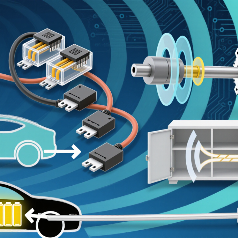
Hall effect sensors detect magnetic fields by measuring a voltage generated across a current-carrying semiconductor. The field pushes charge carriers sideways, creating a signal that internal circuitry amplifies and processes. Different output circuits turn this principle into proportional measurements or discrete switching signals. That distinction matters. A cabinet door detector needs a clear state change, while a sliding control needs continuous position information.
Linear Hall sensors produce an output that varies with magnetic flux density within a specified range. Many analog versions sit near half their supply voltage when no field is present.
Unipolar switches respond to one magnetic polarity and release as that field weakens. Omnipolar switches respond to either polarity, simplifying magnet orientation in some assemblies.
Latching sensors typically require opposite magnetic polarities to change states, making them useful with alternating magnetic poles. Check the datasheet. A latch may retain its previous state after the magnet moves away, which can surprise a door-sensing design.
Selection also depends on operating thresholds, hysteresis, temperature drift, and the magnetic field at the installed sensing location. Hysteresis separates switching and release thresholds, helping prevent output chatter near the switching point. A nominal 3 mm air gap sounds precise, but mounting tolerances can change the field considerably. Choosing by nominal gap alone is tempting; it leaves an important assumption untested. Test the actual magnet, nearby steel, and largest expected gap across the intended temperature range. For linear measurements, also check offset, sensitivity tolerance, noise, and saturation before converting voltage into position.
Defining Measurement Goals and Magnetic Field Requirements
Define the measurement before choosing the sensor. Are you detecting a lid, measuring shaft angle, or tracking current? Specify travel, required accuracy, response time, and operating temperature. Be specific. For example, a 10 mm stroke with 0.1 mm resolution requires 100 distinguishable positions. Resolution alone does not guarantee accuracy; magnet geometry, mechanical tolerances, and temperature also affect the result.
Map the magnetic field at the sensing element throughout the complete movement. Record minimum and maximum flux density, polarity, and field direction. The World Magnetic Model 2020 technical report describes Earth’s main surface field as approximately 20–60 µT. That background matters when measuring weak fields. For an illustrative application producing ±40 mT, a ±50 mT range provides 10 mT of headroom per polarity. However, verify that margin against magnet variation, nearby steel, and temperature changes. For switches, check operate and release thresholds; for linear measurements, examine noise, offset drift, and saturation.
Tips:
Measure the assembled mechanism, including its enclosure and fasteners. Test both travel endpoints and intermediate positions at your expected temperature extremes. Keep raw readings. A provisional 20% field margin can help early selection, but it remains an assumption requiring validation. I would question any selection based solely on a room-temperature measurement or a magnet’s advertised surface strength.
Comparing Sensitivity, Accuracy, Response Time, and Output Options
Choosing a Hall effect sensor starts with the magnetic field available at its actual mounting position. Sensitivity describes how much the output changes as magnetic flux density changes, commonly expressed in mV/mT for analog sensors. Higher sensitivity helps detect weaker fields, but reduces the measurable range when output voltage limits remain fixed. More isn’t always better. For a position sensor, compare readings with the magnet 2 mm and 5 mm away. Accuracy also depends on offset, linearity, temperature drift, and magnet alignment. A sensitive device can still give inaccurate readings beside a warm motor housing.
Response time matters when magnets move quickly or pulses become narrow. For a 100-microsecond magnetic pulse, check propagation delay and minimum detectable pulse width in the datasheet. Check both edges. Rising and falling delays may differ, shifting measured pulse widths. Analog outputs suit continuous position measurements but require an ADC and careful noise management. Digital switches suit threshold detection, while latches usually require opposite magnetic polarities to change states. PWM outputs encode measurements in duty cycle, but filtering and decoding can add latency.
Tips: Test the complete sensor-and-magnet assembly across your expected temperature range. Verify supply requirements, output voltage levels, and any pull-up resistor requirements before connecting your controller. Room-temperature calibration is a useful starting point, though it can hide drift problems. Leave some mounting adjustment; your initial air-gap estimate may need revisiting.
Evaluating Power Supply, Packaging, and Environmental Limits
Power supply requirements deserve more attention than the nominal voltage printed beside a schematic. Consider a 3.3 V rail with ±5% tolerance: it can fall to 3.135 V before transient dips. A sensor requiring at least 3.2 V would already be outside its specified operating range. Check the margins. Compare startup time, average current, and output compatibility, especially when a battery also powers radios or motors. Low average current can hide brief sampling peaks that matter when several devices wake simultaneously.
Packaging affects assembly, magnetic alignment, and protection. A small surface-mount package saves board space, but its sensing element may sit farther from the magnet than expected. That distance matters. Check the specified sensing location against enclosure thickness, adhesive thickness, and mechanical tolerances. For moisture exposure, IEC 60529 specifies a 30-minute temporary immersion test for IPX7 under defined conditions. This rating applies to the tested enclosure; a molded sensor package alone does not establish system waterproofing.
Temperature limits need equally careful reading. The AEC-Q100 qualification document defines Grade 1 operation from −40°C to +125°C and Grade 0 from −40°C to +150°C. These ranges provide useful screening criteria, but they do not guarantee identical magnetic accuracy throughout operation. Compare switching thresholds or sensitivity drift across the actual temperature range. A room-temperature prototype can seem convincing; that remains a weak basis for approving an installation beside a hot motor. Leave room for revision when thermal testing reveals threshold shifts or unexpected heating.