Minimal Space. Maximum Impact! Designed for when every millimeter matters> the new IRONLESS UNANO SERIES
Semiconductors
Increase throughput and precision of your system
Display
Enhance accuracy and precision with linear motors
Science and aerospace
Improve motion quality for a variety of applications
Machine tooling
Robust solutions for increased speed and precision
Digital cutting
Create modular and high throughput applications
Printing
Increase printing speed and quality using linear motors
Robotics
Integrate compact solutions for guaranteed uptime and high dynamics
Life science
Establish precise and clean integrated solutions
Woodworking
Maximize performance and accuracy for high throughput
Stages and system solutions
Compact integration and high performance for your axis
Vacuum applications
Best performance for clean and vacuum applications
Characteristics
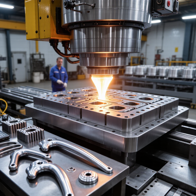
Custom Zinc Alloy Die Casting is a precision manufacturing process for producing strong, detailed metal components at scale. It uses heated zinc alloy, a reusable steel die, and controlled pressure. The result can be a door handle, electronic housing, automotive bracket, or decorative fitting.
The process begins with die design and careful material selection. Engineers review wall thickness, draft angles, cooling channels, and expected loads. Molten zinc is then injected into the closed die at high speed. Pressure fills narrow ribs, sharp lettering, and small openings before the alloy solidifies. After ejection, operators trim excess metal, inspect dimensions, and apply finishing treatments such as plating, powder coating, or painting.
Small details matter. A poorly balanced gate can create air pockets or uneven filling. Excessive pressure may increase flash along the parting line. These defects are not merely cosmetic; they can affect assembly and service life. Experienced manufacturers use process monitoring, sample testing, and coordinate measuring equipment to reduce these risks. However, no casting method is automatically perfect. Tool wear, alloy temperature, and changing production conditions still require attention.
This article explains how Custom Zinc Alloy Die Casting works, from engineering concepts to finished components. It also considers practical limits, quality checks, cost factors, and design decisions. Reliable results depend on more than a powerful machine. They require verified drawings, suitable tolerances, experienced technicians, and honest communication between the customer and foundry.
Custom zinc alloy die casting injects molten zinc into a hardened steel die under high pressure. The process creates thin walls, ribs, threads, and textured surfaces with limited machining. USGS Mineral Commodity Summaries 2024 reported global zinc mine production near 12 million metric tons in 2023. That supply supports zinc’s broad industrial use, although recycled content and regional availability still require verification.
The subtitle matters because Zamak 3, 5, and 7 are not interchangeable. ASTM B86-23 covers zinc alloy castings and chemical requirements. Zamak 3 typically contains about 3.9% aluminum, with very low copper. It offers stable dimensions, good flow, and clean surface detail. Zamak 5 adds roughly 1% copper. Expect higher strength, but slightly reduced ductility. Zamak 7 uses lower magnesium than Zamak 3, improving fluidity for delicate sections and polished finishes. Exact limits should follow the approved material certificate.
In production, engineers check melt temperature, gate design, cooling, and porosity risk. A small venting error can leave a visible blister near a screw boss. That is easy to miss.
The wrong grade can waste tooling time. Strength data from a supplier sheet may also differ from real castings. NADCA process guidance recommends testing representative parts, not relying only on handbook values. For custom work, measure hardness, tensile behavior, coating adhesion, and dimensional change after cycling.
Custom zinc alloy die casting begins with a die designed around the part’s release path, cooling needs, and surface finish. In production, draft angle is not a decorative number. It controls how cleanly the solidified component leaves the steel cavity. A 0.5° draft may suit a short, polished wall with reliable release conditions. Deeper features, textured surfaces, or long cores often need closer to 3°. Small errors can cause drag marks, sticking, or premature die wear. I have seen a drawing pass review yet fail during ejection because texture was added too late.
Wall thickness between 0.8 and 3 mm offers a useful balance between weight, filling, strength, and cycle time. Thin 0.8 mm sections demand controlled metal flow and careful venting. They may cool before the cavity fills. Thick 3 mm areas can shrink unevenly and create sink-like depressions or internal porosity. Ribs, fillets, and gradual transitions help distribute metal without abrupt changes. Sharp corners are troublesome.
The working process usually includes die simulation, tool machining, trial shots, dimensional checks, and production approval. Engineers compare actual parts against drawings, especially around gates, ejector marks, and joining faces. A practical trial should measure draft after coating and finishing, not only in the CAD model. That is an easy oversight. Machining tolerances, alloy temperature, lubricant, and injection speed also influence results. When a 0.8 mm wall is critical, I prefer confirming it with sectioned samples and repeated measurements. The design is not finished when the first part looks acceptable.
Custom zinc alloy die casting uses reusable steel dies to inject molten zinc alloy under pressure, producing precise parts with consistent surfaces and dimensions.
Design reference: Draft angles from 0.5° to 3° support part release from the die, while wall thicknesses from 0.8 mm to 3 mm represent common design conditions for thin, balanced, and robust sections.
Custom zinc alloy die casting begins with carefully measured alloy ingots. The metal is heated to approximately 380–430°C, keeping it fluid without excessive oxidation. The International Zinc Association identifies zinc alloys as suitable for thin walls, sharp details, and high-volume production. That advantage depends on temperature control.
A heated shot sleeve transfers the molten metal into a steel die. Injection pressure commonly ranges from 20–150 MPa, depending on part geometry, wall thickness, and machine design. Higher pressure fills narrow ribs and lettering quickly. It can also increase flash, die wear, and trapped air. Small errors matter. The NADCA Product Specification Standards for Die Castings emphasize process control because dimensional accuracy depends on stable filling and solidification conditions.
After injection, the metal cools inside the die within seconds. Ejector pins then release the casting, while operators inspect seams, pores, and incomplete filling. According to the U.S. Geological Survey Mineral Commodity Summaries 2025, global zinc mine production reached roughly 12 million metric tons in 2024, supporting broad industrial availability. Yet material availability does not guarantee consistent castings. A perfect setting rarely exists. Real production requires adjusting pressure, die temperature, lubrication, and cycle time together. The 380–430°C melting range is only a starting point, not a universal recipe.
Custom zinc alloy die casting uses reusable steel dies to produce precise parts at high speed. Zinc alloys melt near 385°C, according to technical guidance from the International Zinc Association. That relatively low temperature reduces die stress and supports repeated production.
The critical stage is solidification. A typical production cycle lasts 10–30 seconds, depending on wall thickness, part size, and machine capacity. Molten zinc enters the closed die under pressure. It fills narrow ribs, bosses, and textured surfaces within milliseconds. Pressure then remains briefly while heat moves into the die steel. Cooling channels control this transfer. After solidification, the die opens, ejector pins release the casting, and a spray prepares the cavity for another shot. Small parts may approach ten-second cycles. Larger housings usually need longer cooling.
Fast does not mean simple. The North American Die Casting Association’s specification guidance emphasizes controlling porosity, flash, dimensional variation, and ejection marks. A 2024 U.S. Geological Survey report estimated global zinc mine production at roughly 12 million metric tons in 2023, supporting zinc’s broad industrial availability. Yet raw material supply does not guarantee stable casting quality. A gate changed by a few millimeters can alter filling and cooling behavior. The 10-second target can therefore become a poor target. In practice, engineers should validate cycle time with thermal data, sample inspections, and real production measurements. Computer simulations help, but they rarely capture every shop-floor variable.
| Process Dimension | Typical Range or Value | How It Works | Production Relevance |
|---|---|---|---|
| Complete shot cycle | Approximately 10–30 seconds | Includes die closing, metal injection, solidification, die opening, ejection, and die closing preparation. | Supports high-volume production when part geometry, shot size, cooling, and automation are properly balanced. |
| Alloy family | Zinc-based die-casting alloys, commonly Zamak-type compositions | The alloy is melted and injected into a reusable steel die to reproduce the cavity shape. | Zinc alloys provide good castability, dimensional repeatability, surface finish, and thin-wall capability. |
| Melting temperature | Typically about 385–430°C, depending on alloy and process practice | The alloy is maintained in a molten condition before the injection shot. | Lower melting temperatures than many aluminum alloys can reduce thermal stress on dies and help shorten cycle times. |
| Injection method | Pressure die casting, commonly using a hot-chamber machine for zinc | A plunger forces molten zinc through the gooseneck and nozzle into the closed die cavity. | Direct access to molten metal enables rapid, repeatable shots for automated production. |
| Die closing and locking | Completed before injection; locking force is selected for projected part area and pressure | The fixed and moving die halves close, align, and resist separation during metal filling. | Adequate locking prevents flash and protects dimensional accuracy around the parting line. |
| Filling time | Usually measured in milliseconds to fractions of a second | Molten zinc rapidly fills the runners, gates, and cavity before significant freezing blocks the flow. | Controlled filling helps limit cold shuts, misruns, air entrapment, and surface defects. |
| Solidification time | Often a few seconds; strongly dependent on wall thickness and cooling design | Heat flows from the molten metal into the temperature-controlled steel die until the casting is rigid enough to remove. | Solidification is commonly the main portion of the 10–30-second cycle and must be uniform to reduce shrinkage and distortion. |
| Die cooling | Water or other controlled cooling circuits are used where required | Cooling channels remove heat from high-load areas while thermal control maintains a stable die temperature. | Balanced cooling improves cycle consistency, die life, surface quality, and dimensional stability. |
| Die opening | Begins after the casting and runner system have reached adequate rigidity | The moving die half retracts, exposing the casting on the core side or ejector side. | Correct draft angles and die layout help the part separate without sticking or deformation. |
| Ejection | Typically completed within seconds of die opening | Ejector pins push the casting and attached runner system away from the die surface. | Even pin placement reduces bending, drag marks, cracking, and incomplete release. |
| Runner and gate removal | Performed manually, mechanically, or as part of automated trimming | The gate and runner are separated from the finished casting and may be returned to the melt when process controls allow. | Efficient trimming reduces secondary labor and improves material utilization. |
| Typical wall thickness | Approximately 0.5–3.0 mm for many zinc die-cast parts; design-dependent | The die fills thin sections under pressure while maintaining detail and profile accuracy. | Uniform walls promote predictable filling and cooling; abrupt thickness changes can increase defects. |
| Dimensional capability | Tolerances depend on part size, geometry, die design, and inspection method | The reusable steel die provides a fixed reference geometry for repeated shots. | Stable thermal conditions and controlled process parameters are essential for repeatable dimensions. |
| Quality checks | Visual inspection, dimensional measurement, weight checks, and functional testing as specified | Samples or production parts are checked for flash, porosity, short shots, cracks, distortion, and critical dimensions. | In-process monitoring helps maintain stable output during long, high-volume production runs. |

Note: Values shown are typical industry ranges for zinc pressure die casting. Actual cycle time and process settings vary with alloy composition, part size, wall thickness, die design, machine capacity, and cooling strategy.
Custom zinc alloy die casting uses a hardened mold to form detailed metal components at high production speed. After ejection, each part may receive trimming, deburring, polishing, plating, or protective coating. Finishing is not only cosmetic. It can change edge definition, surface size, and functional fit. For critical features, a ±0.05 mm tolerance requires stable tooling, controlled injection conditions, and calibrated measurement equipment. ASTM B86 provides relevant requirements for zinc and zinc-alloy die castings, including material and quality considerations.
Tips: Define critical dimensions before production. Measure them after finishing, not only after casting. Use a coordinate measuring machine for complex profiles, and verify flat areas with suitable gauges. Record temperature, instrument accuracy, and sampling frequency. A polished surface can hide a dimensional problem.
Inspection should combine visual checks, dimensional reports, and material verification. Inspectors may look for flash, cracks, porosity, scratches, and incomplete filling. However, ±0.05 mm cannot be assumed across every feature. Wall thickness, part geometry, mold wear, and coating buildup may affect results. This is where practical judgment matters. A single inspection plan can still miss variation between production batches. Reviewing first-article data and checking later samples is more reliable. ASTM B86 compliance should be supported by traceable records, not a simple claim. Small deviations deserve investigation, even when the part appears acceptable.