Minimal Space. Maximum Impact! Designed for when every millimeter matters> the new IRONLESS UNANO SERIES
Semiconductors
Increase throughput and precision of your system
Display
Enhance accuracy and precision with linear motors
Science and aerospace
Improve motion quality for a variety of applications
Machine tooling
Robust solutions for increased speed and precision
Digital cutting
Create modular and high throughput applications
Printing
Increase printing speed and quality using linear motors
Robotics
Integrate compact solutions for guaranteed uptime and high dynamics
Life science
Establish precise and clean integrated solutions
Woodworking
Maximize performance and accuracy for high throughput
Stages and system solutions
Compact integration and high performance for your axis
Vacuum applications
Best performance for clean and vacuum applications
Characteristics
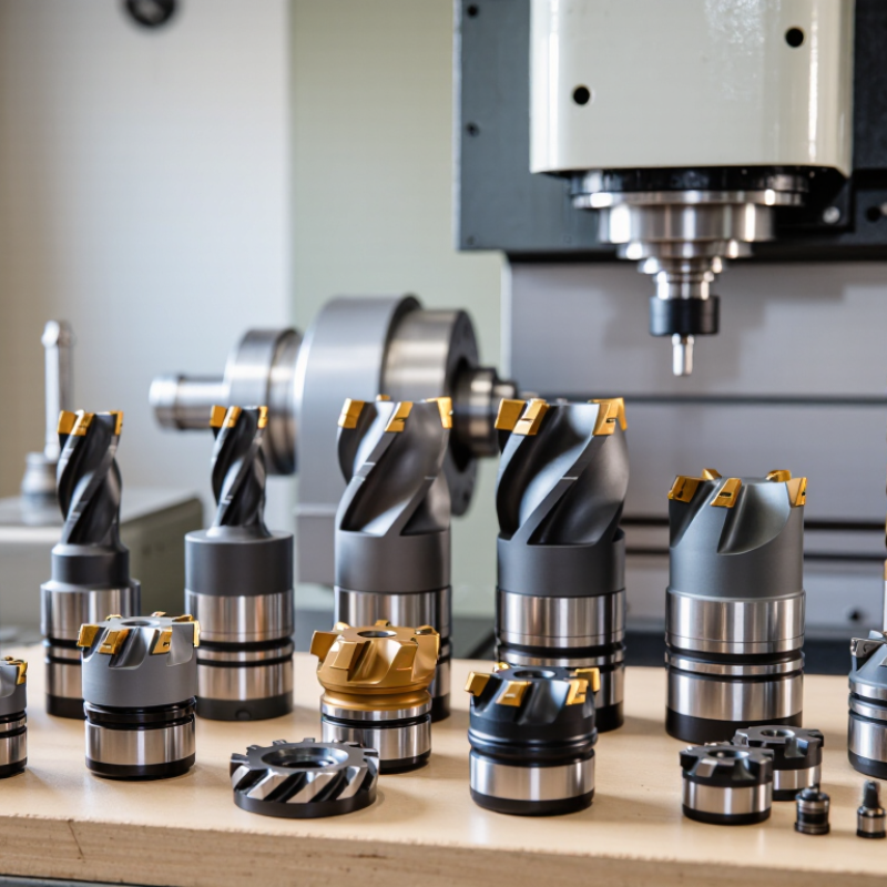
Precision machining is shaped by the tool at the cutting edge. The right choice can improve surface finish, hold a tight tolerance, and reduce unnecessary tool changes. The wrong one may leave chatter marks on a stainless-steel face or wear quickly in abrasive material. Small details matter. This guide to 10 Best CNC Cutting Tools for Precision Machining examines tools commonly used for milling, turning, drilling, and finishing. It considers more than advertised speed or price. Material, machine rigidity, tool geometry, coating, and coolant access all affect performance.
Cnc Cutting Tools are not interchangeable, even when their dimensions look similar. A carbide end mill with the wrong flute design can pack chips in a deep pocket; a suitable geometry may clear them cleanly. For that reason, the selections are framed around practical machining needs, not a universal winner. Not always. Shop conditions differ, and a tool that works well in aluminum may struggle in hardened steel. Readers should check manufacturer recommendations and verify choices with controlled test cuts. That trade-off matters. Tool life and finish can shift with feed rate, workholding, and setup stiffness, so results deserve careful review. The aim is a useful starting point for comparing options, while acknowledging that real machining decisions sometimes require adjustment.
Precision machining begins where the cutting edge meets the material. An end mill with the right flute geometry can leave a clean wall in aluminum, while a suitable carbide drill helps hold a hole’s position and diameter. Face mills remove stock evenly across broad surfaces; reamers refine drilled holes when closer sizing is needed. Small details matter. Tool runout, for example, can make one flute do most of the work, causing uneven wear and a rough finish.
Tool choice also depends on the workpiece, cut depth, machine rigidity, and coolant strategy. A sharp edge may reduce cutting forces in softer alloys, while tougher materials may call for a more wear-resistant grade and steadier feed. Correct speed and feed are not universal settings; operators should check tooling guidance, then verify the cut with measurements and surface inspection. Watch for a changing spindle sound, rising heat, or chips that turn from short curls into long, tangled strands. These clues are useful, but not conclusive. I would not trust a polished surface alone: a part can look accurate and still miss its tolerance. Careful setup, tool condition checks, and measured test cuts make precision repeatable, though they cannot remove every source of variation.
| CNC Cutting Tool | Typical Use and Materials | How It Supports Precision | Selection and Setup Considerations |
|---|---|---|---|
| Solid Carbide End Mill | Slotting, profiling, and pocketing in steels, stainless steels, aluminum, and other machinable alloys. | High rigidity and sharp cutting edges can help produce accurate walls and consistent features when tool deflection is controlled. | Match flute geometry and coating to the work material. Use a suitable stick-out and secure workholding to limit vibration. |
| Indexable Face Mill | Facing broad surfaces on cast iron, steel, and nonferrous metal workpieces. | Multiple inserts remove material efficiently; correct insert height and a stable setup help create a flat surface. | Check insert seating, cutter runout, and insert condition. Cutting parameters depend on the insert geometry and work material. |
| Ball-Nose End Mill | Contoured surfaces, 3D profiles, and curved features in dies, molds, and other components. | The rounded cutting end follows curved geometry and can produce controlled surface finishes with an appropriate step-over. | Effective cutting speed varies with contact point. Consider toolpath direction, step-over, and finishing allowance. |
| Twist Drill | Producing holes in common metals, plastics, and other materials compatible with the drill geometry. | A suitable drill point and stable alignment help establish hole location and maintain consistent hole size. | For deeper holes, use a suitable chip-evacuation strategy. Check drill runout, point condition, and workpiece support. |
| Reamer | Finishing a pre-drilled or pre-bored hole to a more controlled diameter and surface finish. | Its finishing edges remove a small amount of material to improve hole size, roundness, and surface quality. | Leave an appropriate, consistent finishing allowance. Reaming does not correct major hole-position or alignment errors. |
| Boring Bar | Enlarging and finishing internal diameters on milling or turning machines. | Adjustable boring setups can bring an internal diameter to a target size while maintaining concentricity with the setup axis. | Minimize bar overhang and use a rigid setup. Long, slender bars are more prone to deflection and chatter. |
| Tapping Tool | Cutting internal threads in pre-drilled holes in metals and other suitable materials. | A tap forms a thread profile that mates with the specified thread standard and size when correctly aligned. | Use the correct tap-drill diameter, thread specification, and synchronization for the machine. Provide suitable lubrication where required. |
| Thread Mill | Machining internal or external threads, including threads in larger holes and some difficult-to-machine materials. | CNC interpolation controls the thread path and pitch; one tool can often machine different diameters with the same pitch. | Program the correct helical path and account for cutter diameter. Verify thread fit with an appropriate gauge. |
| Turning Tool with Indexable Insert | Facing, straight turning, and profiling cylindrical parts made from steels, stainless steels, cast iron, or nonferrous alloys. | Consistent insert positioning and a rigid toolholder support repeatable diameters and surface finishes. | Choose insert shape, nose radius, and chipbreaker for the operation. Check tool-center height and workpiece rigidity. |
| Parting and Grooving Tool | Cutting grooves or separating parts on a CNC lathe. | A correctly aligned, rigid blade helps maintain groove width and reduce variation during cut-off. | Keep blade overhang short, align the tool accurately, and ensure chips can escape from the groove. |
Choosing a CNC cutting tool starts with the workpiece, not the catalog. Aluminum often benefits from sharp edges and generous flute space, while tougher steels may need stronger edge geometry and heat-resistant coatings. Match the tool material and coating to the alloy, hardness, and cutting temperature. Small details matter. A long, thin end mill may reach a deep pocket, but extra stickout can invite deflection and chatter. Check the tool diameter, flute count, helix, and reach against the feature and machine rigidity.
Consider whether the job calls for roughing, finishing, drilling, or profiling; each operation places different demands on chip control and edge strength. In a narrow slot, too many flutes can trap chips, especially in gummy materials. Chip load matters. Coolant or air, flute design, and chip evacuation should suit the cut. Published speed and feed values are starting points, not promises. Machine power, toolholder condition, runout, and workholding can change the result. Inspect chips and surface finish, then adjust one variable at a time. It is easy to overvalue tool life; cycle time and part quality deserve equal weight. Test the choice on a representative cut before running a full batch.
The 10 best CNC cutting tools for precision machining depend on the material, tolerance, and machine setup. A practical shortlist includes solid-carbide end mills for detailed profiles, indexable end mills for heavier cuts, face mills for flat surfaces, and twist drills for holes. Reamers refine hole size; boring bars correct larger bores. Taps and thread mills produce internal threads, while chamfer mills and grooving tools handle edges and narrow features. Small details matter. Tool runout, workholding, and chip evacuation can spoil an otherwise sound choice.
For precise results, match the tool geometry and coating to the workpiece, then check cutting speed, feed, and tool wear against reliable machining data. The International Federation of Robotics reported 4,281,585 industrial robots operating worldwide in 2023, reflecting broader factory automation, not proving any tool’s accuracy. A 2019 Deloitte and MAPI Smart Factory Study found 86% of surveyed manufacturers expected smart-factory initiatives to drive competitiveness within five years. That context makes repeatable tool changes and process monitoring increasingly relevant. Still, automation cannot rescue a poor setup. This shortlist is imperfect: a rigid machine may favor different tools than a flexible one, and coolant access can change the result. I would recheck the cut.
Matching a cutting tool to the workpiece starts with material hardness and chip behavior. Aluminum usually cuts cleanly with sharp, polished flutes and generous chip space. Stainless steel holds heat, so a rigid carbide end mill, steady feed, and effective coolant can help limit wear. For hardened steel, choose a suitable grade and avoid rubbing at the surface. No tool works equally well across every alloy.
The operation matters just as much. Face mills suit broad, flat surfaces, while smaller end mills handle pockets and shoulders. Drills create holes; reamers refine their size and finish. Thread mills offer control in varied hole sizes, and ball-nose cutters leave curved contours. Thin walls can flex under heavy cutting forces. Reduce engagement and check for chatter before increasing speed. A chart gives a useful starting point, but it may not reflect a worn spindle or an unusual setup.
Tips: Match flute count to chip evacuation needs. Check chips for signs of heat or recutting. Change one setting at a time; that makes results easier to assess. I still find tool selection can involve a little trial and error.
Tool accuracy depends on inspection, cleaning, storage, and consistent setup—not just a sharp cutting edge. Before each shift, wipe the holder taper and inspect inserts under bright light. A tiny chip can leave a repeating mark on a workpiece. Check runout with a dial indicator, then record tool changes, material, feed, and cutting time. Small notes matter.
The U.S. Department of Energy’s Operations & Maintenance Best Practices Guide (2010) estimates predictive maintenance can save 8–12% compared with preventive maintenance, and 30–40% compared with reactive maintenance. These are facility-level benchmarks, not promises of longer tool life. Still, they support condition-based checks. Measure flank wear at planned intervals, monitor spindle load, and replace tools before edge failure damages a finished part. Coolant concentration matters. So does chip evacuation.
Store tools in separate sleeves; loose carbide edges can knock together and chip. Edges chip easily. Verify insert seating and specified screw torque after each change. Avoid polishing away evidence of wear. Inspection intervals need adjustment: abrasive alloys and interrupted cuts wear edges faster than stable aluminum passes. Review scrap, surface finish, and tool-life logs weekly, then revise the schedule. Not every failure is predictable.